SMORE Tutorial - using the profile driven PhantomNet portal
SMORE
This tutorial will walk you through a more advanced experiment built from the basic OpenEPC setup. We will be creating an instance of the prototype for “SMORE: Software-Defined Networking Mobile Offloading Architecture".
This version of the tutorial makes use of the profile driven PhantomNet portal. A version of this tutorial using the classic interface is available here.
SMORE overview

The main goal for SMORE is to allow a portion of mobile traffic to be offloaded to servers located inside the core cellular network without any changes to the functionality of the existing LTE/EPC architecture. To meet this goal, we use SDN to intercept control plane traffic (e.g., UE attaching and detaching packets), which drives the rerouting of data plane traffic to the offload servers.
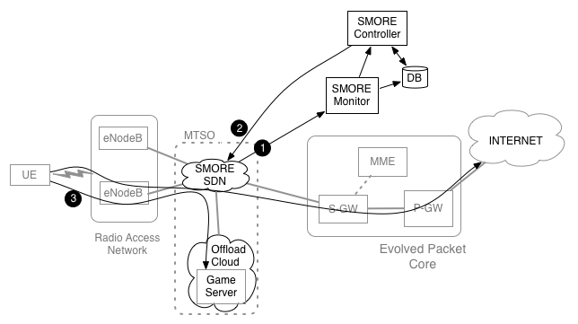
Figure 1 shows the SMORE architecture. To the basic OpenEPC components, this setup adds the SMORE SDN, Controller, Monitor and Offload cloud to realize the SMORE prototype. In Figure 1, we assume an Internet-based service provider, e.g., a gaming provider, who wants to make use of the SMORE service. The SMORE SDN and SMORE Monitor allow the control plane to be continuously monitored (#1 in Figure 1). An attachment event of a registered UE triggers SMORE Controller to install an offloading path for the game server(#2 in Figure 1). When the UE connects to the game server, this traffic will be transparently redirected to the game server in the Offload cloud (#3 in Figure 1). The rest of the UE's data plane traffic takes its usual path out to the Internet.
Experiment topology
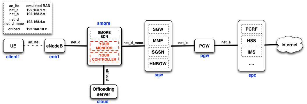
Figure 2 shows the topology of the SMORE prototype in PhantomNet. There are five EPC nodes and two new nodes: (1) SMORE components (e.g., SDN, monitor, and controller ) and (2) Offloading server. Node names appear in blue under the boxes representing them. In the SMORE prototype, the monitor and controller are co-located alongside the SMORE SDN switching functionality on the same machine. The two logical components could be instantiated on other hosts, though this setup reduces the number of resources required on the testbed.
SMORE Experiment Specification
Create a new PhantomNet experiment by logging in to the PhantomNet web UI. If you do not have any current experiments running you should land on the instantiate page by default. (Otherwise you can click on "Actions" and select "Start Experiment" from the drop down menu.) Click on the "Change Profile" button. To find the profile we will use for this tutorial, type "SMORE" into the search box. Select "SMORE-Basic" from the resulting list by clicking on it. This will show a description of the selected profile. Next click on the "Select Profile" button which will take you back to the "1. Select a Profile" page. Click "Next" to reach the "2. Parameterize" page. For this tutorial we will stay with the default options, so simply select "Next" to reach the "3. Finalize" page. This page will show a diagram of the topology that will be created for your experiment. On this page you need to select the "Project" in which the experiment should be created (in case you have access to more than one project). You might optionally also give your experiment a name at this point by typing into the "Name" field. Click "Finish". PhantomNet will now go through the process of creating and setting up your experiment. This will take a couple of minutes, so please be patient. When your experiment goes beyond the "created" state, the web interface will show more information of the resources allocated for the experiment and the current state of each node. For example the "Topology View" tab will show the topology of your experiment and hovering over a node will show its current state.
Note that you have to wait for your experiment as a whole to be in the "Ready" state before you can proceed with the tutorial. (Note: For this profile, status correctly updates in the "Actions->My Experiments" view, while the status in the experiment specific view shows "State: booted (startup services are still running)". When the My Experiments page show status as "ready" you are good to go...)
Using SMORE
After creating a SMORE experiment by using the above profile, you can use SMORE in two modes: (1) Normal L2 switch mode and (2) selective traffic offloading mode.
SMORE SDN as L2 switch mode
In the SMORE prototype setup, we have the smore node inserted between the enodeb and the sgw nodes. The smore node is not setup to perform any forwarding or traffic manipulation by default. So initially no traffic will flow between the enodeb and sgw-mme nodes. To connect these nodes, we turn the smore node into a normal L2 switch mode. This setup will make the experiment function exactly the same as the basic OpenEPC setup and the UE is able to connect to the Internet end-to-end.
The commands below show how to run the smore node as a normal L2 switch. First, “run_ovs.sh“ runs Open vSwitch, and then “start_L2_Switch.sh“ adds the Ethernet interfaces on the smore node to Open vSwitch and inserts OpenFlow flow rules for connecting between enodeb node and sgw-mme node. After running these two scripts, the enodeb node and sgw-mme node will be connected to each other and the UE can attach to the LTE/EPC network and on toward the Internet.
Perform the following commands to enable the L2 switch:
$ cd /opt/binary-smore/L2_switch
$ sudo bash ./run_ovs.sh
$ sudo bash ./start_L2_Switch.sh
Follow the instructions in the "Validating - Functionality" section of the basic OpenEPC tutorial to verify that your UE can connect to the Internet.
To disable the L2 switch functionality:
$ sudo bash ./stop_L2_Switch.sh
SMORE SDN as traffic offloading mode
This section will walk you through the process of running the entire SMORE prototype. Although we provide scripts to automate the process, you may look inside the scripts to understand what they do if you want to. Note that because of how keys are distributed in the experiment you need to access the smore node via the "SSH command" approach (rather than via the "shell tabs" method.)
Perform the following commands to enable SMORE offloading:
$ cd /opt/binary-smore/smore_sdn
$ sudo bash ./run_ovs.sh
$ sudo bash ./start_smore_with_controller.sh
$ cd controller
$ ryu-manager --verbose SMORE_controller
The above commands show the procedures for running the SMORE offloading controller. The first two scripts are almost the same as in the "L2 switch" case, except that “start_smore.sh“ also adds the gtp virtual ports which we implemented in Open vSwitch and does not insert flow rules into Open vSwitch. “SMORE_controller“ will start the SMORE-monitor and SMORE-controller. SMORE-controller first inserts basic flow rules to connect the enodeb and sgw nodes. SMORE-monitor monitors the UE’s attach events and SMORE-controller pushes flow rules into Open vSwitch to support traffic offloading for registered UEs based on information from SMORE-monitor. These procedures are explained in Section 4.1 of the SMORE paper.
Note: To simplify the process the SMORE_controller collects information from other nodes in the experiment. The first time you run the controller you will be prompted to enter "yes" three times to allow the controller ssh access to the other nodes.
Once the controller is running you can test the offloading functionality by performing a UE attach/connect from the UE node (alice).
Currently, the M-TMSI (Temporary TMSI) of registered UEs is used to distinguish registered UEs. The list of registered UEs can be found/modified in the “user.dat” file. If you attach a UE to the network, the SMORE-monitor will print out information about the UE (eg., GUTI, IP address, etc.) and the default bearer set for that UE (eg., GTP tunnel IDs, eNB’s IP, sgw’s IP, etc). The SMORE-controller also shows that it is installing offloading rules if the UE is registered in “user.dat”.
Specifically, the controller will print "Attached UE is a subscriber. Do offloading..." if the detected M-TMSI corresponds to the value in the user.dat file. If the M-TMSI value in the attach is not the same as the value in the user.dat file, the controller will print "Attached UE is NOT a subscriber. Not doing offloading...". In the latter case you can fix the problem by placing the correct M-TMSI value in the user.dat file and re-running the scenario. I.e., stop the controller, edit user.dat, rerun the controller, perform a UE attach. (Note that the controller prints the detected M-TMSI value.)
To verify that offloading is taking place, you can try to ping something on the Internet (e.g., www.google.com) or the offloading server(192.168.10.11) from the UE:
$ ping -c 1 www.google.com
$ ping -c 1 192.168.10.11
If you ping the offloading service (192.168.10.11), the traffic will be diverted by the SMORE mechanisms on the "smore" node to the offloading server instead of taking the default path toward the Internet. RTTs for those replies are significantly smaller (should be less than 2ms) than pinging a normal Internet server since the offloading server is located inside the cellular core network.

