SMORE Tutorial - using the classic PhantomNet portal
SMORE
SMORE overview

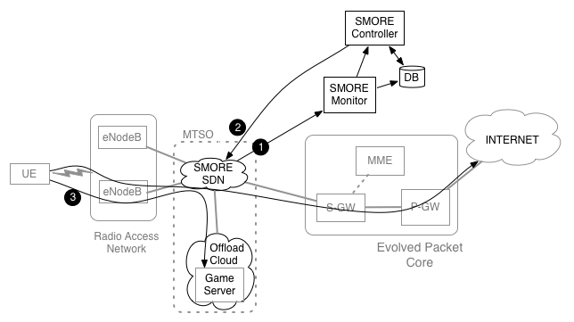
The main goal for SMORE is to allow a portion of mobile traffic to be offloaded to servers located inside the core cellular network without any changes to the functionality of the existing LTE/EPC architecture. To meet this goal, we use SDN to intercept control plane (e.g., UE attaching and detaching packets), which drives the rerouting of data plane traffic to the offload servers.
Figure 1 shows the SMORE architecture. To the basic OpenEPC components, this setup adds the SMORE SDN, Controller, Monitor and Offload cloud to realize the SMORE prototype. In Figure 1, we assume an Internet-based service provider, e.g., a gaming provider, who wants to make use of the SMORE service. The SMORE SDN and SMORE Monitor allow the control plane to be continuously monitored (#1 in Figure 1). An attachment event of a registered UE triggers SMORE Controller to install an offloading path for the game server(#2 in Figure 1). When the UE connects to the game server, this traffic will be transparently redirected to the game server in the Offload cloud(#3 in Figure 1). The rest of the UE's data plane traffic takes its usual path out to the Internet.
Experiment topology
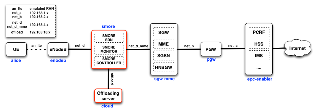
Figure 2 shows the topology of the SMORE prototype in PhantomNet. There are five EPC nodes and two new nodes: (1) SMORE components (e.g., SDN, monitor, and controller ) and (2) Offloading server. Node names appear in blue under the boxes representing them. In the SMORE prototype, the monitor and controller are co-located alongside the SMORE SDN switching functionality on the same machine. The two logical components could be instantiated on other hosts, though this setup reduces the number of resources required on the testbed.

SMORE Experiment Specification (NS file)
Below is the NS script for the SMORE prototype. This NS script is similar to the basic OpenEPC experiment except for two points. First, two new nodes (smore and cloud nodes) have been introduced to the topology and are connected via the “offload” LAN. Second, the SMORE SDN node is inserted as an intermediate node between the enodeb and sgw-mme nodes. Therefore, The enodeb and sgw-mme nodes are connected to the SMORE SDN node via “net d” LAN and “net d mme” LAN, respectively.
Note that the SMORE SDN node uses the “SMORE-IMAGE“ disk image, which is equipped with all SMORE components (e.g., SDN, Monitor, and Controller). “SMORE-IMAGE“ has Open vSwitch 2.0 for switching, ryu controller 3.11, and tshark for the controller and monitor. To support the SMORE prototype, we extended Open vSwitch and the ryu controller. These changes are integrated into the “SMORE-IMAGE“ disk image. You can access all scripts and code(some parts are binary) for the SMORE prototype by downloading our SMORE git repository. With the “SMORE-IMAGE“ image, you can easily use the SMORE prototype. This removes the need to perform complex installations and configuration. However, you are free to put together your own installation/image based on the content of the git repository.
# NS file for instantiating an SMORE prototype setup.
source tb_compat.tcl
set ns [new Simulator]

##################################################################
# OS to use on the nodes. This image must be one that has been
# prepared the way OpenEPC expects!
set OEPC_OS "PhantomNet/UBUNTU12-64-BINOEPC"
# Were to log the output of the startup command on each node
set OEPC_LOGFILE "/var/tmp/openepc_start.log"

# Location of OpenEPC-in-Emulab startup script
set OEPC_SCRIPT "/usr/bin/sudo /opt/OpenEPC/bin/start_epc.sh"

# Number of clients to allocate (currently, value can be 1 or 2)
set num_clients 1

##################################################################
# Code to generate OpenEPC topology and set it up follows.
set nodelist ""
set clientlist "alice bob"

# List of lans that nodes may be added to below.
set lanlist "mgmt net_a net_b net_d net_d_mme an_lte offload"

# Initialize lan membership lists
array set lans {}
foreach lan $lanlist {
    set lans($lan) ""
}

proc addtolan {lan node} {
    global lans
    lappend lans($lan) $node
}

proc epcnode {node {role ""} {clname ""}} {
    global nodelist
    global OEPC_OS OEPC_LOGFILE OEPC_SCRIPT
    uplevel "set $node \[\$ns node]"
    lappend nodelist $node
    tb-set-node-os $node $OEPC_OS
    tb-set-node-failure-action $node "nonfatal"
    addtolan mgmt $node
    if {$role != {}} {
       if {$clname != {}} {
           set startcmd "$OEPC_SCRIPT -r $role -c $clname >& $OEPC_LOGFILE"
       } else {
         set startcmd "$OEPC_SCRIPT -r $role >& $OEPC_LOGFILE"
       }
       tb-set-node-startcmd $node $startcmd
    }
}

if {$num_clients < 1 || $num_clients > 2} {
    perror "num_clients must be between 1 and [llength $clientlist] (inclusive)!"
    exit 1
}


# Create $num_clients client nodes
for {set i 0} {$i < $num_clients} {incr i} {
    set clnode [lindex $clientlist $i]
    epcnode $clnode "epc-client" $clnode
    addtolan an_lte $clnode
}

# Create the epc-enablers node (Mandatory)
epcnode epc "epc-enablers"
addtolan net_a $epc

# Create the pgw node (Mandatory)
epcnode pgw "pgw"
addtolan net_a $pgw
addtolan net_b $pgw

# Create the sgw-mme-sgsn node (Mandatory)
epcnode sgw "sgw-mme-sgsn"
addtolan net_b $sgw
addtolan net_d_mme $sgw

# Create OVS node to interpose on net_d between enodeb nodes and the mme/sgw
set smore [$ns node]
tb-set-node-os $smore "PhantomNet/SMORE-IMAGE"
addtolan net_d $smore
addtolan net_d_mme $smore
addtolan offload $smore

# Offload server
set cloud [$ns node]
tb-set-node-os $cloud "UBUNTU12-64-STD"
addtolan offload $cloud

# Create the enodeb RAN node (Optional)
epcnode enb "enodeb"
addtolan an_lte $enb
addtolan net_d $enb

# Create all lans that have at least two members
foreach lan $lanlist {
    # Since DNS doesn’t officially allow underscores, we have to convert
    # them to dashes in the names of the lans before instantiation.
    set nslan [regsub -all -- "_" $lan "-"]
    if {[llength $lans($lan)] > 1} {
        set $nslan [ns make-lan $lans($lan) * 0ms]
    }
}

tb-set-ip-lan $smore $offload 192.168.10.10
tb-set-ip-lan $cloud $offload 192.168.10.11

# Go!
$ns run
Using SMORE
$ git clone http://gitlab.flux.utah.edu/phantomnet/binary-smore.git
In the SMORE prototype setup, we have the smore node inserted between the enodeb and the sgw-mme nodes. The smore node is not setup to perform any forwarding or traffic manipulation by default. So initially no traffic will flow between the enodeb and sgw-mme nodes. To connect these nodes, we turn the smore node into a normal L2 switch mode. This setup will make the experiment function exactly the same as the basic OpenEPC setup and the UE is able to connect to the Internet end-to-end.
The commands below show how to run the smore node as a normal L2 switch. First, “run_ovs.sh“ runs Open vSwitch, and then “start_L2_Switch.sh“ adds the Ethernet interfaces on the smore node to Open vSwitch and inserts OpenFlow flow rules for connecting between enodeb node and sgw-mme node. After running these two scripts, the enodeb node and sgw-mme node will be connected to each other and the UE can attach to the LTE/EPC network and on toward the Internet. From the directory where you cloned the SMORE repository:
$ cd binary-smore/smore_binary/L2_switch
$ sudo bash ./run_ovs.sh
$ sudo bash ./start_L2_Switch.sh
$ sudo bash ./stop_L2_Switch.sh
This section will walk you through the process of running the entire SMORE prototype. Although we provide scripts to automate the process, you may look inside the scripts to understand what they do if you want to. From the directory where you cloned the SMORE repository:
$ cd binary-smore/smore_binary/smore_sdn
$ sudo bash ./run_ovs.sh
$ sudo bash ./start_smore_with_controller.sh
$ cd smore_monitor_and_controller
$ ryu-manager --verbose SMORE_controller
The above commands show the procedures for running the SMORE offloading controller. The first two scripts are almost the same as in the "L2 switch" case, except that “start_smore.sh“ also adds the gtp virtual ports which we implemented in Open vSwitch and does not insert flow rules into Open vSwitch. “SMORE_controller“ will start the SMORE-monitor and SMORE-controller. SMORE-controller first inserts basic flow rules to connect the enodeb and sgw-mme nodes. SMORE-monitor monitors the UE’s attach events and SMORE-controller pushes flow rules into Open vSwitch to support traffic offloading for registered UEs based on information from SMORE-monitor. These procedures are explained in Section 4.1 of the SMORE paper.
Note: To simplify the process the SMORE_controller collects information from other nodes in the experiment. The first time you run the controller you will be prompted to enter "yes" twice to allow the controller ssh access to the other nodes.
Once the controller is running you can test the offloading functionality by performing a UE attach/connect from the UE node (alice).
Currently, the M-TMSI (Temporary TMSI) of registered UEs is used to distinguish registered UEs. The list of registered UEs can be found/modified in the “user.dat” file. If you attach a UE to the network, the SMORE-monitor will print out information about the UE (eg., GUTI, IP address, etc.) and the default bearer set for that UE (eg., GTP tunnel IDs, eNB’s IP, sgw’s IP, etc). The SMORE-controller also shows that it is installing offloading rules if the UE is registered in “user.dat”.
Specifically, the controller will print "Attached UE is a subscriber. Do offloading..." if the detected M-TMSI corresponds to the value in the user.dat file. If the M-TMSI value in the attach is not the same as the value in the user.dat file, the controller will print "Attached UE is NOT a subscriber. Not doing offloading...". In the latter case you can fix the problem by placing the correct M-TMSI value in the user.dat file and re-running the scenario. I.e., stop the controller, edit user.dat, rerun the controller, perform a UE attach. (Note that the controller prints the detected M-TMSI value.)
To verify that offloading is taking place, you can try to ping something on the Internet (e.g., www.google.com) or the offloading server(192.168.10.11) from the UE:
$ ping -c 1 www.google.com
$ ping -c 1 192.168.10.11
If you ping the offloading service (192.168.10.11), the traffic will be diverted by the SMORE mechanisms on the "smore" node to the offloading server instead of taking the default path toward the Internet. RTTs for those replies are significantly smaller (should be less than 2ms) than pinging a normal Internet server since the offloading server is located inside the cellular core network.
