OpenEPC Tutorial - using the classic PhantomNet portal
Foreword and Prerequisites
We now have two ways for experimenters to interact with PhantomNet. The Classic PhantomNet interface uses the original Emulab interface and makes use of NS files to specify the experiments. The (new) PhantomNet interface makes use of profiles, developed for the Apt testbed, to specify experiments. Under-the-hood both interfaces provide access to the same resources. Note, however, that over time new features will be developed primarily for the new profile driven interface.
This version of the tutorial shows how to interact with PhantomNet via the Classic PhantomNet interface. A version of this tutorial using the profile-based interface is available here.
PhantomNet sits atop Emulab, and relies on the latter for a much of its core testbed functionality. We reuse much of the Emulab terminology as well (such as "experiment", "swap-in" and "swap-out"). PhantomNet diverges as it gets into the particulars of mobile components and functionality, which is the primary focus of this document (as it relates to OpenEPC).
For the classic PhantomNet interface we also use the Emulab experiment configuration specification language. Via this interface PhantomNet experiments utilize much of the same specification syntax and semantics as Emulab. If you run into unfamiliar terms in this tutorial, please look through the Emulab tutorial for explanations and definitions.
You might also want to familiarize yourself with OpenEPC by reading through the OpenEPC documentation.
Basic OpenEPC Setup
This guide will walk you through the detailed steps necessary to create a basic 3GPP LTE/EPC network. Such a setup consists of user equipment (UE), an EnodeB, Serving Gateway (SGW), Packet Gateway (PGW), Home Subscriber Server (HSS), Mobility Management Entity (MME), and some other supporting services. The goal of this portion of the tutorial is to have the UE connect to the Internet via the PhantomNet-provisioned LTE/EPC network.
Overview:

Experiment Specification (NS file):
# Basic OpenEPC NS specification file.
source tb_compat.tcl

set ns [new Simulator]

# OS to use on the nodes. This image must be one that has been prepared the way OpenEPC expects!
set OEPC_OS "PhantomNet/UBUNTU12-64-BINOEPC"

# Were to log the output of the startup command on each node
set OEPC_LOGFILE "/var/tmp/openepc_start.log"

# Location of OpenEPC-in-Emulab startup script
set OEPC_SCRIPT "/usr/bin/sudo /opt/OpenEPC/bin/start_epc.sh"

# Number of clients to allocate (currently, value can be 1 or 2)
set num_clients 1

##############################################
#
# Code to generate OpenEPC topology and set it up follows.
#

# Some top-level lists - don't change these directly unless you know what you are doing.
set nodelist ""
set clientlist "alice bob"

# List of lans that nodes may be added to below.
set lanlist "mgmt net_a net_b net_d an_lte"

# Initialize lan membership lists
array set lans {}
foreach lan $lanlist {
  set lans($lan) ""
}

proc addtolan {lan node} {
  global lans
  lappend lans($lan) $node
}

proc epcnode {node {role ""} {clname ""}} {
  global nodelist
  global OEPC_OS OEPC_LOGFILE OEPC_SCRIPT

  uplevel "set $node \[\$ns node]"
  lappend nodelist $node
  tb-set-node-os $node $OEPC_OS
  tb-set-node-failure-action $node "nonfatal"
  addtolan mgmt $node
  if {$role != {}} {
    if {$clname != {}} {
      set startcmd "$OEPC_SCRIPT -r $role -h $clname >& $OEPC_LOGFILE"
    } else {
      set startcmd "$OEPC_SCRIPT -r $role >& $OEPC_LOGFILE"
    }
    tb-set-node-startcmd $node $startcmd
  }
}

# Quick sanity check.
if {$num_clients < 1 || $num_clients > [llength $clientlist]} {
  perror "num_clients must be between 1 and [llength $clientlist] (inclusive)!"
  exit 1
}

# Create $num_clients client nodes
for {set i 0} {$i < $num_clients} {incr i} {
  set clnode [lindex $clientlist $i]
  epcnode $clnode "epc-client" $clnode
  addtolan an_lte $clnode
}

# Create the epc-enablers node (Mandatory)
epcnode epc "epc-enablers"
addtolan net_a $epc

# Create the pgw node (Mandatory)
epcnode pgw "pgw"
addtolan net_a $pgw
addtolan net_b $pgw

# Create the sgw-mme-sgsn node (Mandatory)
epcnode sgw "sgw-mme-sgsn"
addtolan net_b $sgw
addtolan net_d $sgw

# Create eNodeB (Mandatory)
epcnode enb "enodeb"
addtolan an_lte $enb
addtolan net_d $enb

# Create all lans that have at least two members
foreach lan $lanlist {
  # Since DNS doesn't officially allow underscores, we have to convert
  # them to dashes in the names of the lans before instantiation.
  set nslan [regsub -all -- "_" $lan "-"]
  if {[llength $lans($lan)] > 1} {
    set $nslan [ns make-lan $lans($lan) * 0ms]
  }
}

# Go!
$ns run
- The procedure "epcnode" is used to declare an EPC node instead of a normal node.
- The procedure "addtolan" is syntactic sugar for adding a node to a particular EPC LAN.
- Even a basic an LTE/EPC experiment needs at least five nodes: UE, eNodeB, SGW, PGW, and EPC-enabler.
Instantiating and Validating
To make sure the NS script does its job correctly, we'll need to check the connectivities among nodes using ping. eNodeB, SGW, PGW, and EPC-enablers should be able to ping each other. Note that the UE so far is not connected to the network and the Internet as it has not attached to the EPC network. After an attaching procedure (described below), the UE will connect to the eNodeB and be able to ping the others and the Internet. Note that because of the network setup between the OpenEPC nodes you cannot directly access the UE (node alice) or the PGW (node pgw) via the PhantomNet/Emulab control network. To reach these to nodes first ssh to the PhantomNet "users" control node (users.phantomnet.org) and then ssh to the alice/pgw nodes.
Only making sure the connectivity among nodes is not enough; EPC software has to be running on nodes to make the whole thing work. To make sure the correct EPC software is running on the corresponding node, you can log into the node and check for any wharf/ser services:
/opt/OpenEPC/bin/listepc.sh
Running the above command on the each Emulab node should return something like what is shown in Table 1.
| Emulab node | EPC logical instances |
|---|---|
| alice | mm |
| enodeb | enodeb |
| sgw-mme | hnbgw, mme, sgsn, sgw |
| pgw | pgw |
| epc-enabler |
aaa, andsf, bf, cdf ,cgf, hss, icscf, pcrf, pcscf, pcscf.pcc, scscf, squid rx client |
Table 1. OpenEPC instances in each Emulab node
OpenEPC instances can be started and stopped by running the appropriate start, stop or kill scripts.
To start an instance run:
sudo /opt/OpenEPC/bin/[element_name].start.sh
E.g., to start the PGW on the pgw node run:
sudo /opt/OpenEPC/bin/pgw.start.sh
sudo /opt/OpenEPC/bin/pgw.stop.sh
sudo /opt/OpenEPC/bin/pgw.kill.sh
yourhost> ssh -Y users.phantomnet.org
... MOTD ...
you@users> ssh -Y alice.<your_experiment>.<your_project>.emulab.net
ForwardAgent yes
ForwardX11 yes
ForwardX11Trusted yes
StrictHostKeyChecking no
Protocol 2
/opt/OpenEPC/bin/mm.attach.sh
mm.list_networks
mm.connect_l3 LTE
mm.disconnect_l3 LTE
Attaching the UE to the network using the GUI (alternative to the text-based console):
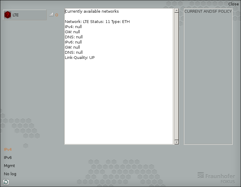
Once logged into "alice", start up the OpenEPC mobility manager GUI by running "/opt/OpenEPC/mm_gui/mm_gui.sh". This will bring up a window that looks like this:
Click on the "LTE" button with the red icon in the left hand column. You should see status messages go by on the text console, and the red icon should turn green. The line at the top should now read "mm-state-attached":
Notes:
- if you click the LTE button again, it should disconnect the alice client (and the icon should turn red once more). You can either close the mobility manager GUI client, or minimize it. Closing the GUI will not disconnect the UE from the EPC.
- Sometimes the GUI does not properly show the MM's state after clicking on the toggle button (e.g., it still shows red (detached)). There is a refresh button in the lower left-hand corner of the GUI window that you can click to update the display.
From your shell into the "alice" client, try pinging out to a host on the Internet, use wget to fetch something, and use internet browser after downloading browser, etc. Traceroute will show you that the connection jumps through some internal connections in the EPC network. When the "alice" client is connected, you should be able to see the associated session from the OpenEPC web interface by navigating as follows:
"E-UTRAN" top tab -> "EnodeB" sub-tab -> "Sessions" left-hand menu item -> Click "Search" button on form (no params) -> click the only listed session's IMSI (should be "001011234567890").
Miscellaneous Notes
- OpenEPC logical instance (service) consoles
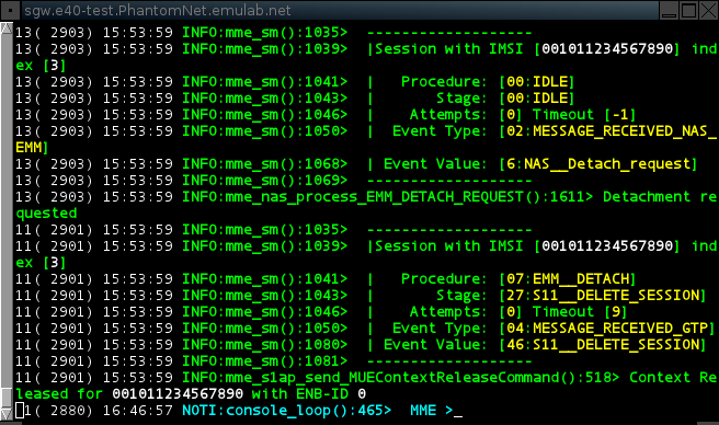
You can have a look at the individual OpenEPC component consoles by going to the respective node hosting the component of interest (e.g., the MME), and typing "/opt/OpenEPC/bin/<component>.attach.sh".
/opt/OpenEPC/bin/pgw.attach.sh
Ctl-a d
Use the command shown above on this page to see the list of active EPC services. These consoles are particularly useful for debugging.
- Useful console/CLI commands
gw_bindings.print
- OpenEPC setup hooks in PhantomNet
The PhantomNet harness that configures and starts the appropriate OpenEPC services based on node role (see above), is tied into the end of the boot process. So, rebooting any node should ultimately trigger OpenEPC service startup. Note that OpenEPC components are quite tolerant of service restarts and temporary outages (reconnecting when possible).
- Indirect connectivity to mobile clients and the P-GW
- OpenEPC configuration
(Use username: "admin" and password: "epc").
Each OpenEPC logical instance (service) also has its own XML configuration file, which is located under /opt/OpenEPC/etc. We hope to have heavily annotated versions of these XML files in the not-too-distant future.
- Network configuration


